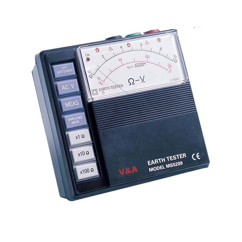


Broadly speaking, “earth resistance” is the resistance of soil to the passage of electric current. Actually, the earth is a relatively poor conductor of electricity compared to normal conductors like copper wire. But, if the area of a path for current is large enough, resistance can be quite low and the earth can be a good conductor. It is the earth’s abundance and availability that makes it an indispensable component of a properly functioning electrical system. earth resistance meter is used to measure the earth resistance.
Measuring ranges:
Earth resistance 10/100/1000Ω
Earth voltage 30V AC (5KΩ/V approx.)
Accuracy:
Earth resistance Within ±5% of full scale
Earth voltage Within ±5% of full scale
Measurement system:
Earth resistance
By constant current inverter.
800Hz approx,2mA
Earth voltage
By rectifier type
5KΩ/V approx,40~500Hz
Withstand Voltage: 1500V AC for one minute between electrical circuit and housing case.
Self-Check facility: Lead wire connection to C and P terminals and proper auxiliary earth resistance can be checked by pressing “BATT.CHECK” button. “OK” lamp is illuminated.
Batteries: 8pcs. 1.5V AA battery or equivalent
Dimensions: 140(L)×140(W) ×90(D)mm
Weight: 800g approx.
Accessories: Test leads (red-15m,yellow-10m,green-5m) Auxiliary earth bars carrying case.
Earth resistance is measured in two ways for two important fields of use:
1. Determining the effectiveness of “ground” grids and connections that are used with electrical systems to protect personnel and equipment.
2. Prospecting for good (low resistance) “ground” locations, or obtaining measured resistance values that can give specific information about what lies some distance below the earth’s surface (such as depth to bedrock).
Test leads (red-15m,yellow-10m,green-5m) Auxiliary earth bars carrying case.
